
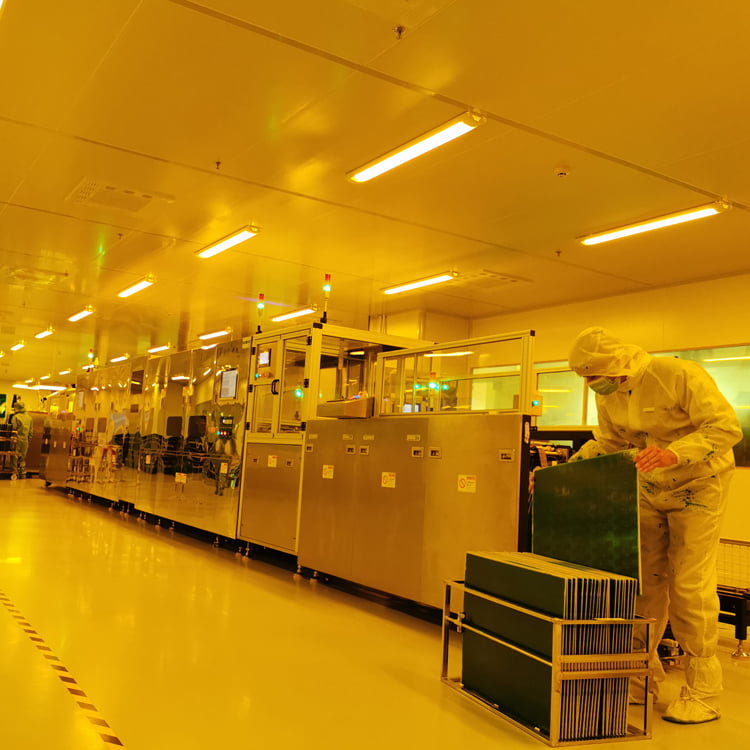
Problem: You invested in automation to reduce errors, but still face costly defects. Agitation: This happens because your line just follows commands, it doesn't think. Solution: A truly intelligent line adapts to real-world problems on its own.
The most advanced LDI lines operate not just as automated machines, but as intelligent systems. They use dynamic scaling compensation to counteract material distortion, closed-loop logic to self-regulate developing processes, and zero-downtime changeovers for unmatched flexibility. It's a shift from simple motion control to dynamic process control.
I've spent over 15 years in this industry, and I've seen "automation" mean many things. For a long time, it just meant connecting machines with conveyors. But that's not enough anymore. The real challenge isn't just moving a PCB from point A to point B. The real challenge is ensuring the thousandth board is as perfect as the first, even when no one is watching. Let's explore what makes an LDI line truly intelligent, not just automated.
How can an LDI line overcome material distortion without human help?
Problem: Every PCB material expands and contracts with temperature and humidity.1 Agitation: This tiny, invisible distortion is a major cause of layer-to-layer misalignment and scrapped HDI boards.2 Solution: The system must measure and compensate for this distortion on every single board.
An intelligent LDI line uses a dynamic compensation system. It scans hundreds of micro-alignment points on each board to create a unique distortion map3. The system then alters the exposure data in real-time to perfectly match the board's current state4, ensuring flawless registration without any manual intervention.
Let's think about this like a veteran technician with 20 years of experience. A basic machine just reads four corner fiducials and assumes the board is a perfect rectangle. But our system knows better. It knows that after multiple lamination cycles, an HDI board isn't a perfect rectangle anymore5. It has complex, non-linear local distortions. Our line acts like that experienced technician, carefully inspecting the entire board. It uses a "multi-point local compensation algorithm" to measure hundreds of points, understanding that the top-left corner might have shrunk while the bottom-right has stretched. It then applies "Sub-block Scaling," performing micro-adjustments to different areas of the exposure pattern. It’s not a one-size-fits-all correction; it’s a custom-fit solution for every single board. This is the only way to guarantee the μm-level precision required for today's complex, any-layer HDI designs6.
| Feature | Standard Alignment | Dynamic Scaling Compensation |
|---|---|---|
| Measurement Points | 4 corner fiducials | Hundreds of micro-points |
| Distortion Model | Linear (assumes uniform stretch) | Non-linear (maps local distortion) |
| Correction Method | Global Scaling | Sub-block Scaling |
| Best For | Standard Multilayer | High-Density Interconnect (HDI) |
Can an automated line maintain perfect developing quality 24/7?
Problem: Your developer's concentration and temperature naturally fluctuate during a long run7. Agitation: This leads to inconsistent line widths, side-etching, and impedance control failures8, especially on unmanned overnight shifts. Solution: A system that actively manages the process, not just monitors it.
Yes, through a true closed-loop process control. Onboard sensors continuously monitor chemical parameters. When a change is detected, the system doesn't just stop and alarm; it instantly adjusts process variables like conveyor speed or spray pressure to maintain perfectly consistent developing results around the clock.
This is where the line’s intelligence really shines. It’s about creating a link between different stages of the process. For example, the system knows that fine lines on high-multilayer boards require a precise energy dose. It uses a "real-time light intensity feedback loop9" to monitor the laser's power. If it detects a slight drop in power, it automatically adjusts the scanning speed to ensure the dry film receives the exact millijoules of energy needed10. This is what we call "Dose Compensation."
This intelligence extends to the developing stage. Based on the circuit density data it just processed during exposure, the system tells the developer how to behave. For dense HDI boards where impedance control is critical, it enables "multi-stage pressure auto-adjustment." This "upstream data guiding the downstream process" integration allows for precise side-etch control, keeping impedance tolerance within the required ±5%11. It’s like having your best process engineer watching over every single board, ensuring consistency from the first to the last.
Isn't a fully automated line too rigid for high-mix orders?
Problem: Your factory is facing a flood of high-mix, low-volume (HMLV) orders. Agitation: Traditional automation is terrible at this, with long changeover times that kill your productivity. Solution: An automated line that can switch jobs faster than a human.
On the contrary, an intelligent line provides ultimate flexibility. With "Zero-Downtime Changeover," a simple barcode scan instantly loads the new job file and all associated process parameters. The changeover happens in seconds, not minutes, making it the perfect solution for HMLV production and rapid delivery.
This capability gives you true "production elasticity." But this intelligence is also about protecting your investment and your yield. High-multilayer boards are prone to warpage after repeated thermal cycles.12 A warped board entering a high-precision machine is a recipe for disaster. It can cause out-of-focus exposure or, even worse, a collision that destroys a very expensive laser head. Our system has a final line of defense: "laser height measurement with real-time auto-focus." High-precision displacement sensors map the topography of every board in milliseconds. As the board moves, the system drives the lens on the Z-axis, making it "dance" over the warped surface to maintain perfect focus at all times. This feature is not a luxury; it is an essential safeguard for your assets and your yield in a fully unmanned environment.
| Task | Manual Changeover | Zero-Downtime Changeover |
|---|---|---|
| Initiation | Manual program loading | Automated barcode scan |
| Parameter Setup | Manual entry and verification | Instant loading from Job File |
| Test Runs | Often required | Not necessary |
| Total Time | 15-30 minutes | < 1 minute |
Conclusion
A truly intelligent, fully automated LDI line does more than just move boards. It thinks, senses, and adapts using dynamic compensation, closed-loop process control, and instant changeovers for ultimate production elasticity.
A materials standard, university source, or laminate reliability paper can confirm that PCB base materials expand or contract with heat and moisture. ↩
A PCB manufacturing guideline or HDI reliability paper can support the connection between substrate distortion, registration error, and rejected boards. ↩
A technical paper or patent literature overview can show that multipoint alignment is used to characterize and compensate board distortion. ↩
A source on maskless lithography or LDI registration control can verify that digital exposure patterns can be scaled or locally corrected. ↩
A PCB fabrication or reliability source can explain how lamination heat and pressure affect dimensional stability. ↩
An IPC document, university note, or HDI design reference can substantiate the precision requirements for fine-line and microvia registration. ↩
A process-control reference can confirm that developer chemistry and temperature are monitored because they vary and affect results. ↩
A PCB fabrication or controlled-impedance source can support that conductor geometry variation affects impedance and yield. ↩
A lithography or laser-control source can show that light-intensity feedback is used to maintain consistent exposure dose. ↩
A dry-film photoresist technical reference can confirm that exposure dose is specified and affects imaging quality. ↩
A standards-based or educational reference can clarify whether ±5% is a common or specified controlled-impedance tolerance. ↩
A reliability paper or IPC-related source can support that thermal cycling and layer stackup stresses contribute to PCB warpage. ↩